Standard properties of steel buildings

Iron and steel supports for structures
March 9, 2022
The use of iron and steel in the steel structures
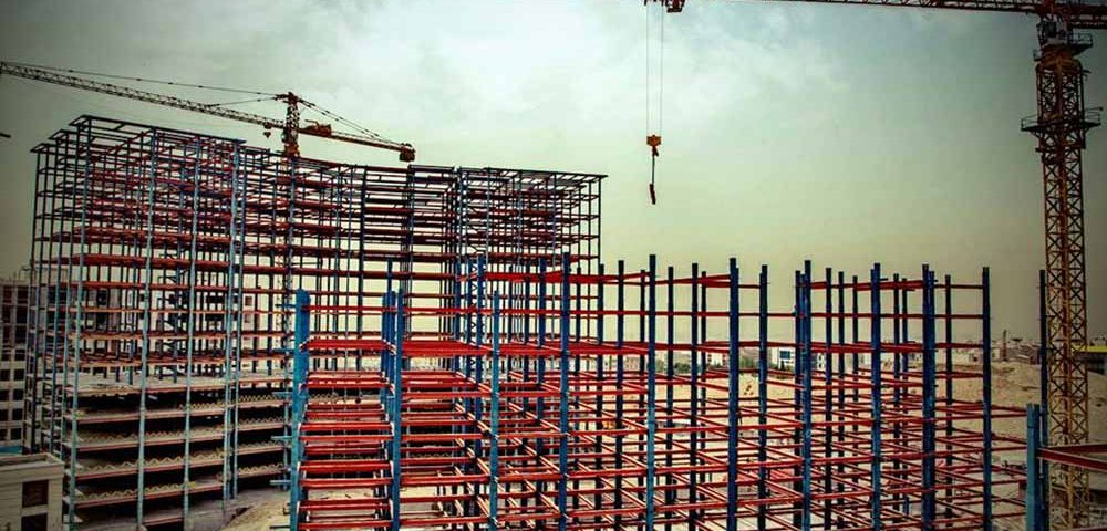
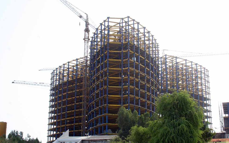
March 9, 2022The basic frame of the steel building includes columns to support the side walls and roof, construction of rigid I-beams to achieve optimal strength. The material used has a resistance of at least 50,000 p.s.i. However, some manufacturers use materials with a strength of 35,000 p.s.i that are not strong enough. By using a material with higher strength, a smaller web can be used, which means saving space during design.
The frames are buried individually and with continuous arches that are welded with an automatic welding machine (this helps with quality control). A factory cover is used to protect them during the installation process. Frames and columns are made of cold rolled, hot rolled sections or “I” shaped beams depending on the design needs in the construction of the steel frame.
Secondary frame of the building
The protrusions and ridges (on the roof) are 8 inches or 10 inches to meet the design needs. Cold-rolled Z-sections have a strength of 13 to 16 ga. Materials that have a resistance of 5500 p.s.i according to ASTM A-570 provide the highest resistance. The protrusion system overlaps with the columns, creating a continuous beam that ultimately produces additional resistance. The hinges are mounted on the roof and have a range of 2 to 6 inches to provide strength and save labor costs during installation.
The maximum distance between the cotyledons in the center is 5 inches. The belts are a cold-rolled C-section that provide a good ground for resistance to various weather conditions. Sheet Angle is a continuous coating angle that is used to install the sheets in the building to facilitate installation operations. The base angle is a continuous angle used to connect the base of the sheet to the concrete. These concretes are joined together by equivalent supports or anchors.
Diagonal rods or cable braces for ceilings and walls are used to remove longitudinal loads from the structure. The flange bracing angle is provided to attach the rigid frame to the protrusions and hinges. This ensures that the allowable compressive strength is provided for each combination of loads. The Purlin assembly angle in the center is selected so that the distance between the Purlin and the stiffeners is determined accordingly.
Sheetting
Materials with a standard functional strength of 80,000 p.s.i. Some manufacturers use less resistant materials that are less resistant to other effects. All galvanized steel coils (1.25 oz-hot dipped) on each side help prevent damage to the steel sheet. The deep serration at the top provide more resistance to the cross section. Optional semi-hidden panels with “Shadow Line” configuration are available for walls, building systems, soft materials, etc. to add beauty to the building.
Connectors
Construction screws are used in accordance with ASTM standards. A-325 is used for primary frame connections and A-307 for secondary frame. Self-drilling and self-tapping joints are used before assembly with neoprene washers and metal caps to help ensure strength and impermeability.
Coatings
Closed cell neoprene strips with adhesive support are used to help insulate the building. To help seal the weather, these strips were placed on the slabs and roof of the building. More packages and insulation may be added to the floors if needed. Prefabricated sections may also be used to match insulation configuration panels. 1.5-inch Notch sheets on a concrete base are also designed in all buildings. These sheets are a barrier to air penetration into empty buildings.
Sealants
Sealants are used to protect the side edges of the roof, for roofs, covers and to provide adequate insulation.
Thin edge panel
The long, thin-edged panels adjust the slope and characteristics of the adjacent roof panels to help ensure convergence and weather resistance. Prolonged coverage should be applied to prevent water from penetrating into the building.
Cutting style and gloss
Corners and edges in all buildings should be covered with standard materials. It is also a barrier to moisture, insects and pollution.
Plans and drawings
Retaining screw designs, construction reactions for foundation design, installation guide, and engineering certification are provided shortly after the building deposit is submitted. General building instructions and step-by-step design instructions for assembly are also provided. Valid engineering designs are also provided, including wall and ceiling diagrams, cross sections, sheets and their details. These drawings clearly show the proper installation and assembly of all building components. Part numbers are written on all components (except screws). These numbers are provided in accordance with the detailed list in the construction plans and the transport list to assist in the assembly of the building.


